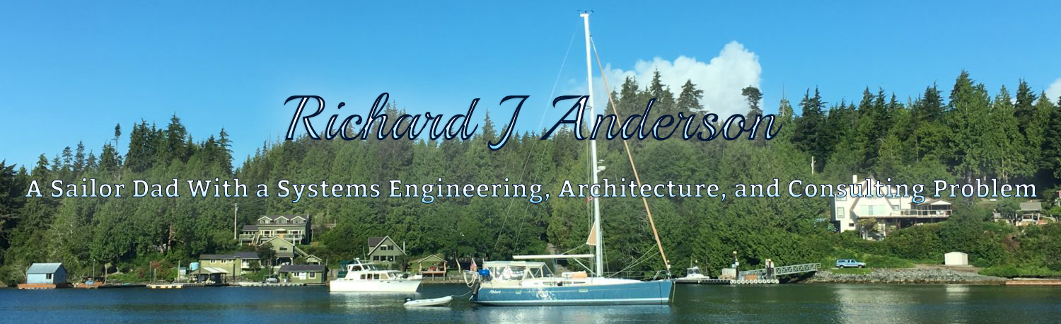
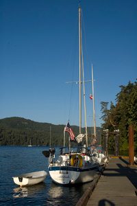
The Cal 2-29 is a Bill Lapworth design and is a cruiser/racer class sloop.
Specs:
- LOA – 29.34 ft

- LWL – 24 ft
- Beam – 9.25 ft
- Draft – 4.5 ft (fin keel)
- Displacement – 8000 lbs
- Ballast (lead keel) – 3350lbs
- Sail Area – 434 sq ft
- Theoretical Hull Speed – 6.6 knots (we’ve clocked 9kts with GPS and knotmeter)
- Sail Area to Displacement Ratio – 17.36 (pretty good ratio for performance)
- Displacement to LWL – 258 (cruiser/racer)
- Farymann A30M Diesel Inboard w/Nanni 2:1 Reduction transmission (12HP 1-Cyl)
- Cal 29 Owners Guide (’75 and ’77)
- Cal 2-29 Standard Equipment List
- Cal 2-29 Mast Spec’s (’77 2-29)
- Cal 2-29 Dimensions and Weights
- Cal 2-29 Prop Strut
- Cal 29 Farymann A30 Prop Shaft
- Cal 29 Rigging Dimensions
- Cal 29 Color Brochure
- Cal 29 (Infamous) Beam Drawing
- Cal 29 Stainless Beam Photo
- Mariposa Sailing (External Website)
- Renewal Time and Me (External Website)

Cal 2-29 Line Drawing
Keb Gawry
November 2, 2016 at 10:37 am
Hi Richard, My name is Ken and I believe I contacted you maybe 7 months ago with questions about my Cal29. I now have a new problem. About 2 months ago, I grounded it on some rocks. After getting pulled off, I looked for any damage and found under the step/access panel to the battery/ engine compartment, some separation of the sides to the front panel, also, a little more water than normal coming in. Upon pulling the boat out for winter storage, the only visible damage was two dings in the keel about the diameter of a softball. There were no visible cracks.The invisible problem, the keel is now loose to where it will swing sideways. Not to where it looks like it will fall off, only maybe an 2 inches in either direction.
After posting this issue on the Cruisers and Sailors forum, one of the responders stated that to his knowledge, the keel is built right into the hull and the 3400 lb lead ballast is dropped into the keel and filled over with whatever material they used. Being involved in the construction industry, the various ways that I figured out to repair this issue, such as stripping all the glass off the ballast and then trying to re-glass it to the hull, all appear to be expensive to the point where the insurance company would consider it totalled considering the age and agreed value.
I would love to avoid this for various and obvious reasons to which I’m sure your aware of. With that said, I have come up with another solution I would like your opinion on, especially considering your architectural and engineering background. What if we drilled let’s say,eight or ten long holes down into the keel from the bilge and then filled them with metal rods.
Does this sound like a feasible, effective repair for this situation? What diameter and length should the rods be? What type of metal? Any other suggestions would be much appreciated. This is a great boat that we have we paid $3500.00 for and have invested another 5 or 6K in upgrades. I would hate to loose her. Thanks for any input.
Ken
[email protected]
November 7, 2016 at 8:57 am
Wow, Sorry to hear about this.. First, I must provide a disclaimer that I am in no way qualified to recommend structural repairs to a boat. You should probably consult a naval architect or reliable boat yard..
However, I will comment on a couple things from my own experience with our Cal 2-29..
1.) On our boat, the bilge area under the batteries and engine is completely isolated from the rest of the bilge. There is no way for water to drain out, so ANY water that gets in there is stuck there. Ours had a big manual bilge pump mounted in front of the batteries that we periodically used to empty that section when there was water. To my knowledge the only sources of water in that area are:
a.) The prop shaft packing
b.) The raw water lines and pump for the motor
So my suggestion there is to pump out that area and see if more water is coming in, and try to identify the source. I believe the reason for the isolation is in the event of oil or fuel leaks, the oil/fuel won’t drain down to the lower bilge and get pumped out to sea.
2.) Regarding the keel. Ours had a little wobble, maybe an inch or two, the entire time we owned it. IT was never an issue. The hull fiberglass form includes the keel area and the lead is encapsulated inside. The structural reinforcement for the keel seems to be primarily the stringers across the bilge and the fiberglass itself.
There are several cases of people running into issues with the keel wobble becoming excessive and having to repair it. Our naval architect contact suggested that we could build/reinforce the stringers under the floor, possibly with some carbon fiber, if it became a problem.
I don’t believe there is any need to internally reinforce the lead itself. If I recall correctly, some owners stripped the bottom paint off and found cracks around the keel to hull joint area, so they reinforced with fiberglass, faired, and repainted. If you have separation of stringers inside the boat, you may need to tighten that all up and reinforce the joints with glass or carbon.
I don’t see any reason to strip all of the glass off the keel, and in fact I would think that would cause structural impairment beyond what you might have currently.
All that said, you may not actually have any structural issues, the keel movement may be normal for the age, so work through the easy stuff first (stuffing box and engine raw water system to identify any sources of water), and possibly strip away some of the bottom paint around the area that the keel meets the hull and check for cracking and flexing there.
Also, I believe the Cal_List on Yahoo Groups has several members that have dealt with this themselves.
bill palmer
April 16, 2019 at 2:49 pm
Richard,
I saw the note about keel wobble. My Cal 29 suffers the same malady. I am the third owner and have had the boat since the 1980s. It has been checked by a glass/structural repair shop. They did not seem overly concerned, though I am becoming uncomfortable with it as it makes the deck unstable to stand on and it seems to be worsening.
However, your discussion is about a 2-29, which apparently has some manufactured structural framing under the floor that adds strength to the keel-to-hull area, is of interest. I believe all the 29s were manufactured as a one piece hull layup in the mold. Ballast was then placed inside the keel and glassed over. There is no joint between the keel and hull. My 29 (hull 133) has no framing at all other than the bulkhead and inside liner located over the front and rear of the keel. Could you confirm that the 2-29 has some cross-hull framing under the cabin sole, aft of the mast step and forward of the companion way step? If so, I might pursue the glass shop installing some similar structure. I know it would be expensive, but the current situation is more than annoying.
John Stricklett
January 13, 2017 at 1:53 pm
Hello Richard,
I recently purchased a 1978 Cal 2-29 and I found the standard equipment list on your site very helpful.
I have a 1978 with the dining table that swings up and bolts to the main bulkhead and two settees. Is that the version of the 2-29 that you have? I also have the Atomic 4.
– John
[email protected]
January 14, 2017 at 1:07 pm
Do you have a starboard side inline galley and two quarter berths? Or an L galley and one quarterberth? If you have the L galley, and a single quarterberth only, along with a swing up dining table, I believe that means you have a 3-29, which a handful were made near end of production.
I am not aware of any swing up tables on 2-29’s, though I could just not be remembering correctly.
Our 2-29 had a table on a post, and we had a short post to swap in for converting to a dinette. We had the Farymann A30M in ours, single cylinder 12HP diesel. Very simple but worked well.
John Stricklett
January 16, 2017 at 10:31 am
Richard,
I must actually have the Cal 3-29. It is the L-Galley with one quarter birth. It is Hull # 1005. Probably one of the last ones made. It has the Atomic 4 – which must have been an option instead of the Diesel. The L-Galley opens up the interior and was probably done to counter competitors, who were opting for this design. It does complicate access to the engine. The boat needs some upgrading, but the overall fit and finish is very good. The boat had a FAMET furler, which is still functional, but I may go with something of newer design. I think your site is very helpful, especially if you end up with a boat with little background information from the owner.
– John
Steve Kibble
July 7, 2017 at 11:08 am
I’m looking at buying a 29 with wheel steering, that I would like to convert to tiller. Do you have any info about this type of job, or can you point to any online resources? Thanks in advance.
Darrell Street
January 23, 2018 at 5:02 pm
The rudder stock port for a tiller vessel, is a heavy tube of GRP between the the hull up to the cockpit sole where the tiller cap is mounted to the top of the rudder stock which is schedule 40 SS pipe). This GRP rudder tube must have a segment chopped out for the installation of the wheel steering quadrant and a stuffing box bonded in to seal out seawater. I assume the cut out and the stuffing box are not included on a tiller boat, but not sure. The rudder’s stock is likely cut down a bit to make it flush to the cockpit sole for the wheel steering installation (since it is only accessed for an emergency tiller use), so you would want a rudder with a full length stock and the trunnion fitting for the top to take the tiller. As you would probably not want to modify the rudder port, you would want to add some sort of seal mechanism where the rudder tube emerges through the sole to keep deck water out of the boat.
Jim
May 17, 2018 at 6:57 pm
Some useful info, here. Thanks! FYI, these links no longer work: Mariposa Sailing (External Website)
Renewal Time and Me (External Website)
Jim
May 17, 2018 at 6:58 pm
PS. I believe the standard prop shaft diameter for a Cal 29 was one inch, yes?
mobius981
September 7, 2018 at 10:59 am
Hello all,
I am a sailor, and I am reaching out for a dear friend. He recently bought a Cal 2-29 without spreaders. We are looking for specs so he can have them built. Bit of a daunting task, lol.
He has a 1974 Cal 229 with HIn CAB 29573 0474 573
If any of you have or know of a 1974 CAL 229 he would like to get dimensions of the spreaders and particularly if boat is in the pacific northwest. He would happily come out and do measurements. Best would be a boat with HIN starting with CAB. i suspect a CAL 29 would do as well!
GTW Richard I appreciate your spec page and have printed out a couple for my friend!!
Many thanks and I hope to hear from you!!! Any advice much appreciated!!!
mobius981
Hans Kunst
September 14, 2018 at 4:23 pm
Have you tried “sailboat wrecking yard” In Lynden Wa? I believe he has a cal 29 on there lot.
bill palmer
April 16, 2019 at 2:03 pm
Did you receive dimensions for the spreaders? I have a pair I took off of mine and can measure if you like. Its the original 29, but I expect the dimensions are the same, at least in terms of length. I patterned and made new ones from the old ones using Sitka Spruce. They have been on the boat for at least 5 years, no problems.
Rich
April 16, 2019 at 2:32 pm
I don’t have dimensions for the spreaders, if you could send along that would be great and I’ll get the details online for others.
Bill palmer
October 18, 2019 at 7:17 am
Sorry, just noticed your mail. Dimensions for spreaders:
38 3/4 x 4 1/4 x7/8”
Aluminum plates bolted to spreader reinforce wood at mast end and attach to mast with SS pins secured with cutter pins. Outer end has brass strap around end of spreader for shroud to fit into, this secured by small SS wire.
chaz
October 27, 2020 at 8:52 pm
Did you get those spreaders made? I could use a pair too and I’m in the PNW.
Carl Brooke
November 14, 2018 at 2:20 pm
Hello John. I just snapped the rubber coupler on the drive line where the prop shaft connects to the back of the engine. Do you know a source for replacements? 1974 Cal 2-29 Faryman A 30.
Rich
November 14, 2018 at 4:34 pm
The supplier (PRP-Inc) that used to have the flex coupler (Part#159-0075) seems to be out of business. Their website is gone now. Other than them, the only other option I know of is to find one from an old motor, which may be hard to do. You could have something similar custom made, or possibly get a newer style and modify the mount to make the newer poly disc fit in there.
Carl Brooke
November 15, 2018 at 7:04 am
I cant find the part anywhere. Do you think it would be ok to just eliminate it and bolt direct to the shaft without it. Cant seem to find any manufacturers who make something equivelent.
Frank Mitchell
October 17, 2019 at 5:51 pm
I have one that I’m not using because I repowered my Cal 2-29. It was a replacement about 18 years ago but was only used for about a year or two.
Darrell Street
April 16, 2019 at 8:59 pm
The rubber flexible couplings used for the Farymann model A30M are unusually long (about 4″ ) and if deleted, the prop will probably locate ahead of the P-bracket. There is mention in the Farymann repair manual (pg. 73) that if the shaft has a flexible stuffing box, a flexible coupling should not be used.
A basic engine installation theory states that only two of three items should be flexible. These include the engine mounting, the shaft stuffing box and the prop shaft coupling. Since most all recent installations include flexible mounting for the engine, this requires a flexible stuffing box so by this rule the shaft coupling should be a solid one.
When I converted to a Yanmar 2GM20F engine/transmission replacing the Farymann (an interesting story on its own), I decided to go with a solid shaft coupling. This has worked well for us with a very flexibly mounted engine. It saves money and space too. Having a flexible coupling there to act as a safety fuse to limit torque should the prop get wrapped is another matter.
Protection for the transmission is a selling point but I am more concerned for the shaft or P-bracket getting bent.
If the flex coupling is the ‘expendable’ type, then a spare should be carried or space available for the shaft to slide forward when it is removed. The Farymann flex coupling tears in two unlike some modern flex couplings (PYI, etc.). Perhaps an email to the present Nanni company through the USA engine importer could find answers or maybe a source of couplings. I know that the dimensions of this Nanni coupling is quite unlike those of more common engines which flex couplings are made for. I wonder if it might match with a modern Nanni engine.
Darrell Street
April 18, 2019 at 11:16 am
Just to finish up an this tricky coupling problem, PYI is a dealer for R&D Marine who makes more typical flexible couplings (but not apparently for the Nanni/Farymann coupling). Since going to a solid coupling is suggested above by me, it would require, in most cases, a longer propeller shaft or an adapter made to fill in the space of the original coupler. This could be made of strong aluminum (if kept as a full cylinder) by a good machine shop. If a longer shaft is planned then you might use a split shaft coupling by R&D as they probably can custom machine the coupling face to the Nanni specs.
To read up more on this broken rubber coupling dilemma (from 2008), see http://www.cruisersforum.com/forums/f114/replacement-flex-coupling-14047-2.html
It may still be feasible to buy these from Germany. Note that there are both 3 bolt and 4 bolt versions.
Luis Adrian Gonzalez
October 23, 2019 at 1:03 pm
Hello, Richard. My buddy and I have a 1969 Cal 29, currently on the hard in Gloucester Va. We’re preparing it for passage down to Costa Rica, where we currently reside. We just discovered an important leak in the potable water holding tank. As far as we can tell so far, the only way to get to the tank so we can repair it calls for removal of the fore bulkhead..all the way down to the hull. So I’d like to ask you, and / or any other sailor here, before we go tearing into it…is there any other way to access and repair the tank? I thank you in advance for your kind reply , insight and advice.
Philip Spuler
March 25, 2020 at 8:18 pm
Luis, Just saw this post. Did you fix your tank? I also have a 1969 Cal 29 #110. I have been putting off maintenance on my water tank but will probably be getting to it this season. My plan was to start hacking up the V berth sole till I could get to it then patch it back together. I’m would be interested in hearing your approach.
K.G.
April 22, 2020 at 10:38 am
I removed my water tank by opening up the berth. Trickery but will come out and back in. (Had a leak in weld)
Norway’s Ark, Hull #3
Ken Gawry
February 1, 2021 at 10:01 am
Hello everyone. I have a 1970 Cal 29 and I am trying to restore the windows. Any Ideas as to where to get the rubber extrusion that is on the inside part of the frames. All the window repair companies here in Cleveland are clueless.
pspuler
March 27, 2022 at 4:40 pm
Ken, I salvaged as much of that as I could when I removed the old lights. It was all stiff and worthless BUT I cut a few small pieces that seemed to still resemble rubber and used them as spacers to position the new acrylic in the frame. Taped everything off and sealed it with a good calk the acrylic shop recommended.
No leaks yet.
Good luck getting them out next time though 😬.
I’d rather fight that than leaks, so we are happy.
Taio
March 19, 2022 at 4:53 pm
Anyone know what the bore diameter on the prop strut is for a 1976 cal 2-29? It’s not on the drawing linked above
Taio
March 20, 2022 at 8:02 am
Also the stern tube od?
Darrell
March 20, 2022 at 4:25 pm
My 1973 model the strut uses a cutlass bearing with 1.25″ OD.
I run with a 1″ stainless shaft for a yanmar 2GM20F.
Dion
August 3, 2022 at 9:50 am
Hi I’m looking for engine parts for my ‘76 cal 2-29, specifically a head gasket. It’s got the ‘74 A30 Farymann diesel. I’m not having much luck finding parts
Rich
August 3, 2022 at 10:41 am
Have you tried these guys? http://www.farymann.com/service.php